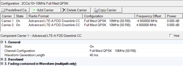
The General table in the downlink carrier node enables you to turn the downlink carrier on and off, select a saved channel configuration, and view the length of the generated waveform.
Additional parameter setup tables for the downlink carrier are described in Baseband (Advanced LTE-A FDD Downlink) and Fading (Advanced LTE-A FDD Downlink).
Double-click or use the drop-down menu to turn the carrier off or on.
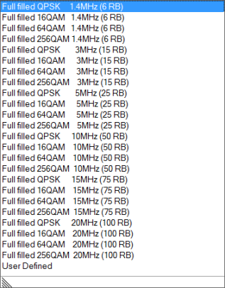
Select a channel configuration with the desired modulation
type, bandwidth, and number of resource blocks (RB)
from the  drop-down list.
The setting is not selectable until certain parameters are changed (e.g. in the node: State, Auto Symbol Rolloff Length Configuration, Baseband Filter; and in the Downlink node: Total Number of Antennas, System Bandwidth, ...) then is automatically set by the software.
Range: 10 to 160 ms (Multicarrier) or
10240 ms (Single Carrier)
Default: 40 ms
Enter a value in milliseconds for Waveform Generation Length. Total Sample Points is based on the selected Waveform Generation Length and Oversampling Ratio as shown below:
Total Sample Points = Base Sampling Rate (MHz) × Oversampling Ratio × 1000 × Waveform Generation Length (ms)
If the Waveform Generation Length parameter is set less than the Transmission Configuration Length, the value of Transmission Configuration Length is changed to be ≤ Waveform Generation Length. In summary, the relation between Transmission Configuration Length and Waveform Generation Length is that the Transmission Configuration Length ≤ Waveform Generation Length. (For more information on the Transmission Configuration Length parameter refer to the Channel Setups Advanced LTE-A FDD UL and DL topics.)
While the long waveform is playing, the following signal or data values are generated sequentially.
Downlink:
SFN in BCH is automatically counted up until the end of the waveform.
HARQ Process scheme in DL-SCH is automatically updated until the end of the waveform.
Payload data in DL-SCH is sequentially used for transport block until the end of the waveform.
HARQ Process Index and New Data Indicator (NDI) in DCI contents are automatically updated until the end of the waveform.
Figure 1 shows the generic frame structure.
Figure 1. Generic radio frame structure